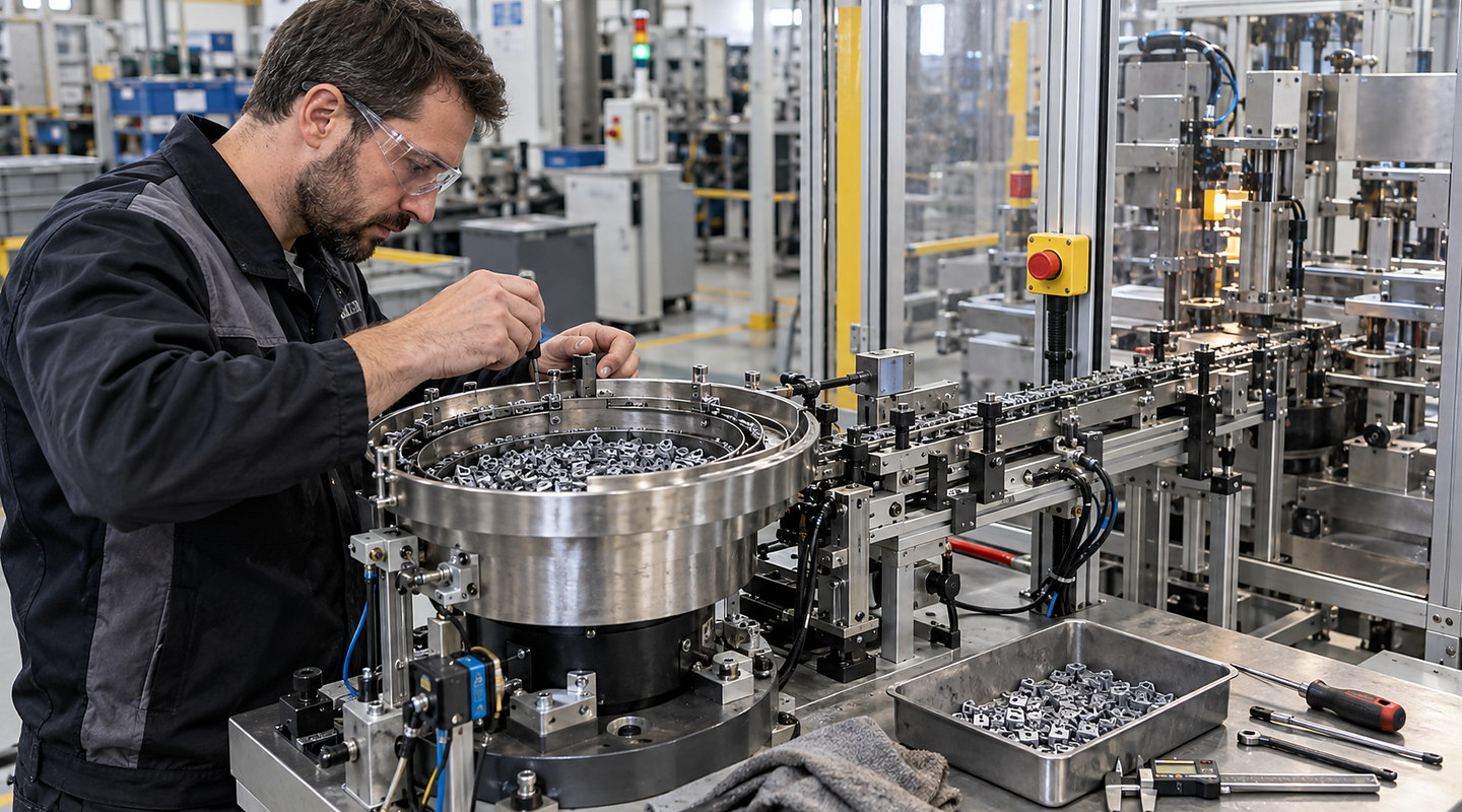
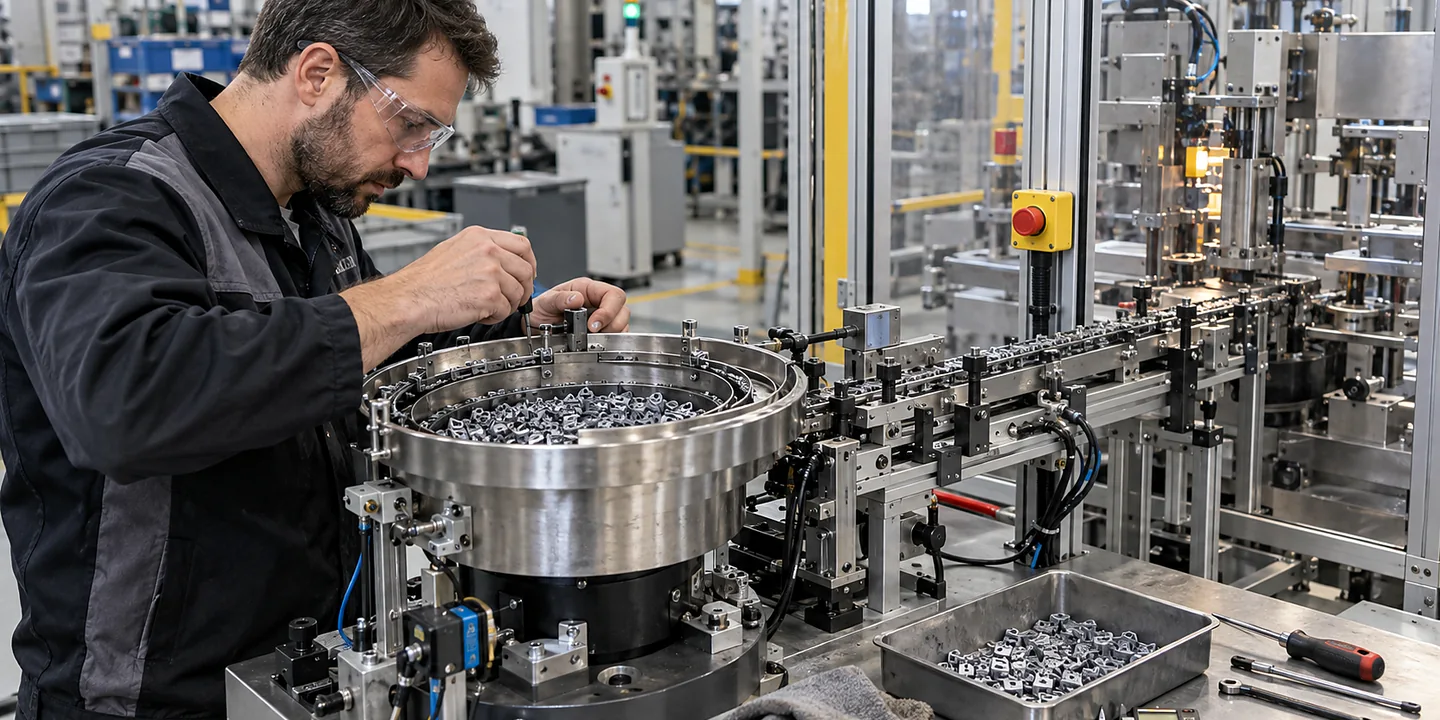
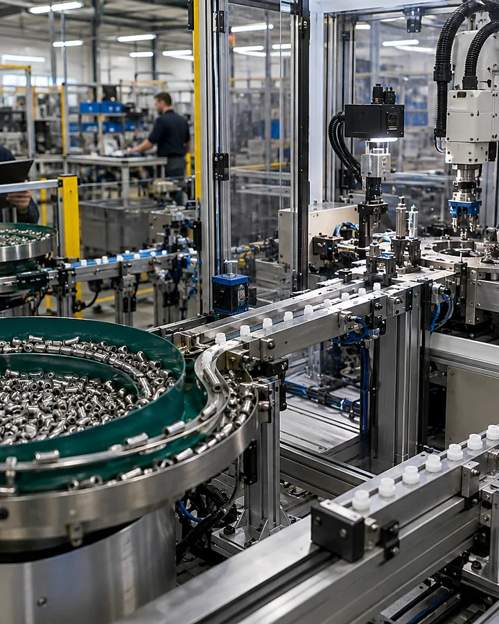
A bowl feeder controller governs the feeder drive and its response to production demand. For a replacement or new integration, identify the drive, sensor arrangement and control signals before comparing adjustment features or connector types.
Speak directly with Sorting Solutions about vibratory bowl-feeder control systems.
Quick answer
Which controller suits our feeder drive and production-control interface?
Record the feeder drive details, existing controller, sensor arrangement and required start-stop signals. Explain whether the line needs level control, recipe settings or remote speed adjustment. Check the proposed controller against the actual drive and wiring, and agree how settings and fault states will be documented for operators.
Application decisions
Specify the controller, drive and demand signals together
Decision 1
Identify the actual feeder drive
Photograph the drive and controller nameplates and provide the existing wiring information. Record supply, drive ratings and manufacturer references. A similar enclosure or plug does not establish electrical compatibility; the proposed combination needs to be checked against the equipment documentation.
Decision 2
Separate bowl, track and hopper control
List each driven device and whether it needs an independent output. Describe how the hopper replenishes the bowl and how the linear track calls for parts. Treat an overfilled bowl and a full discharge track as different conditions with different responses.
Decision 3
Define what each sensor means
Show sensor positions and the meaning of occupied, clear and fault states. Agree any delay used to prevent repeated start-stop switching around a moving queue. Include the response to a disconnected sensor or a track that stays blocked.
Decision 4
Agree the PLC interface
Document the required start permission, running indication, fault signal and any remote adjustment. Confirm signal types and ownership before wiring changes are made. Operational demand signals and safety functions need distinct definitions in the machine control design.
Decision 5
Make settings recoverable
Record the accepted settings for each approved part recipe and identify who may change them. Where backups or parameter exports are supported, include them in the handover. A replacement should be recoverable from documented settings rather than operator memory.
Decision 6
Trial the operating sequence
Check start-up, empty supply, blocked discharge, replenishment and restart after interruption with representative components. Record accepted feeding behaviour at the receiving machine. See the controller integration considerations when defining the machine interface.
Applications
Control steady feeding and changing demand
A dedicated bowl and track may need different control behaviour from a line with variable demand. Describe the driven devices and their sequence before comparing controller features.
From equipment records to repeatable feeder control
01
Capture the existing equipment
Collect nameplates, wiring, parameter records and the reason for replacement or upgrade.
02
Agree a compatibility review
Check the proposed drive and controller pairing, channels, sensors and required line signals.
03
Commission the feeding sequence
Set up the agreed demand and replenishment behaviour using actual parts and downstream conditions.
04
Hand over settings and faults
Retain the accepted parameters, wiring revisions and operator responses to normal alarms.
Important limits
Know what needs a separate check
Sample trials must include normal, marginal and supplier-variant components.
Quoted feeder output is not the same as usable delivery at the downstream process.
Fragile, flexible, magnetic or entangling parts may need a different presentation method.
Your final solution for vibratory bowl-feeder control systems must reflect the law, current standards and site-specific risks that apply to your installation.